

Kirchhoff’s Laws & Circuits
NCERT Chapter 3 (Part 2) • Cells, Networks & Wheatstone Bridge
1. Cells, EMF, and Internal Resistance
EMF ( ): The potential difference between the positive and negative terminals of a cell when no current flows through it (open circuit).
Internal Resistance ( ): The finite resistance offered by the electrolyte inside the cell to the flow of current.
 ):
):
When a current  is drawn from the cell, the potential difference is less than EMF:
 .
.
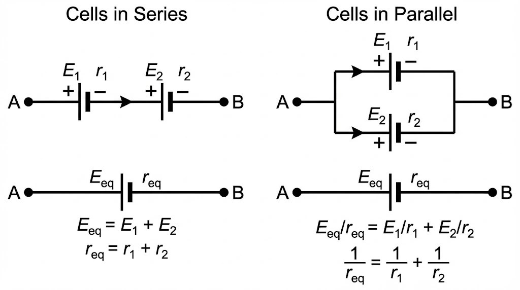
2. Derivation: Cells in Series
Consider two cells ( ) and (
 ) connected in series (end-to-end) between points A and C.
Let
 and
and  be potentials at the terminals. For the first cell:
 .
.
Similarly, for the second cell connected between B and C:
 .
.
The potential difference across the combination (A to C) is the sum:

Rearranging terms:
 .
.
If we replace the combination with a single cell of
 and
and  , the equation would be:
 .
.Comparing the coefficients:
 and
and  .
.
3. Derivation: Cells in Parallel
Consider two cells connected in parallel between points  and
and  . Currents
  and
and  flow out of the positive terminals.
By conservation of charge (junction rule), the main current
splits: .
.
Since they are in parallel, the terminal voltage
is the same for both cells.For cell 1:
 .
.For cell 2:
 .
.
Substitute
and into the current equation: .
.
Multiplying by
 and rearranging to isolate :
 .
.
Comparing this with the standard equation
 , we get:
 and
and  .
.
4. Kirchhoff’s Rules
For complex circuits where Ohm’s law isn’t sufficient, we use Kirchhoff’s Rules.
At any junction, the sum of currents entering equals the sum of currents leaving.
 .
.
The algebraic sum of changes in potential around any closed loop is zero.
 .
.
5. Solved Example: Kirchhoff’s Rules
Let’s apply Kirchhoff’s rules to solve a typical circuit problem (Based on NCERT Example 3.6).
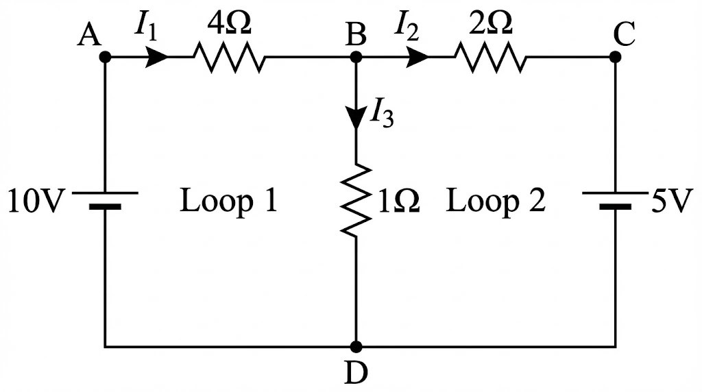
Find currents , , and  in the circuit where resistors are
  and batteries are
  .
.
Current entering = current leaving:
 → Equation (1)
Start at A, go clockwise: through 10V battery → 4Ω → 1Ω → back to A.
– Voltage rise: +10V (battery)
– Voltage drop:
 (across 4Ω, with current)
– Voltage drop:
(across 1Ω, since flows downward, same as loop direction)So:
 →
→  → Equation (2)
Start at B, go clockwise: through 2Ω → 5V battery → 1Ω → back to B.
– Voltage drop across 2Ω:
 (current is in direction of loop) →
– Voltage drop across 5V battery: going from **+ to –** → voltage drop →

– Voltage across 1Ω: we’re going **upward**, against
→ this is a **voltage rise** → 
So:
 →
→  → Equation (3)
From Equation (1):
→ Substitute into Equation (2): →
→  →
→  → Equation (4)
Now use Equation (3):
→ Multiply by 2:  → Equation (5)
Add Equation (4) and Equation (5):
 →
→  →
→ 
Plug into Equation (3):
 →
→  →
→ 
Plug into Equation (1):

 means the actual direction of current is **opposite** to what was assumed (i.e., from C to B, not B to C). This is physically possible and common in circuit analysis. The 1Ω branch carries significant current () because the 5V battery “pushes” against the 10V side, creating a potential difference that drives current through the middle branch.
6. Wheatstone Bridge
An arrangement of four resistors used to measure an unknown resistance accurately. It consists of four arms (R1, R2, R3, R4) and a galvanometer.

 ).
).Apply loop rule to ADBA (assuming
):
 .
.
Apply loop rule to CBDC:
 .
.
Dividing the two equations:
 .
.
Ready to test your knowledge? Try 10 solved numericals on Electrostatic Potential & Capacitance: Click here →
Also practice the Question Bank