
Electrostatic Potential & Capacitance
NCERT Chapter 2
Weightage: ~9 Marks
JEE Main: ~2 Qs
Jump To Section:
| Topic | Question Type | Marks |
|---|---|---|
| Derivation: Potential due to Point Charge | Short Answer | 2 Marks |
| Derivation: Potential due to Dipole | Long Answer | 5 Marks |
| Derivation: Parallel Plate Capacitor | Short Answer | 3 Marks |
| Derivation: Energy Stored | Short Answer | 2 Marks |
1. Electric Potential
Electrostatic potential  at a point is defined as the work done by an external force in bringing a unit positive charge from infinity to that point (without acceleration).
Definition
 SI Unit: Volt (V) = Joule/Coulomb

Derivation 1: Potential due to a Point Charge
3 Marks

Step 1: Electrostatic Force
Consider a source charge at origin. Force on unit positive test charge at distance :
 at origin. Force on unit positive test charge at distance
  :
:

Step 2: Work Done
Work done by external force against this repulsion to move by :
 :
:

Step 3: Integration
Total work done from to :
 to
to  :
:
![W = -\int_{\infty}^{r} \frac{Q}{4\pi\epsilon_0 (r')^2} dr' = -\frac{Q}{4\pi\epsilon_0} \left[ -\frac{1}{r'} \right]_{\infty}^{r}](https://i0.wp.com/physicsqanda.com/wp-content/ql-cache/quicklatex.com-b6920af82d16f736ca024be4e6547bb9_l3.png?resize=296%2C28&ssl=1 "Rendered by QuickLaTeX.com")
Final Result


Relation between E and V:
Electric field is the negative gradient of potential.
(Field flows from high to low potential).
 (Field flows from high to low potential).
Derivation 2: Potential due to an Electric Dipole
5 Marks

Step 1: Superposition
Potential at P due to (at ) and (at ):
 (at
(at  ) and
) and  (at
(at  ):
):

Step 2: Geometry (Cosine Rule)
For :
 :
:


Step 3: Substitution
![V = \frac{q}{4\pi\epsilon_0 r} \left[ \left( 1 + \frac{a \cos\theta}{r} \right) - \left( 1 - \frac{a \cos\theta}{r} \right) \right]](https://i0.wp.com/physicsqanda.com/wp-content/ql-cache/quicklatex.com-1cbc37b2c6045818ee8365c914efc349_l3.png?resize=288%2C24&ssl=1 "Rendered by QuickLaTeX.com")

Final Result
Using Dipole Moment :
 :
:

2. Equipotential Surfaces
An equipotential surface is a surface with a constant value of potential at all points.
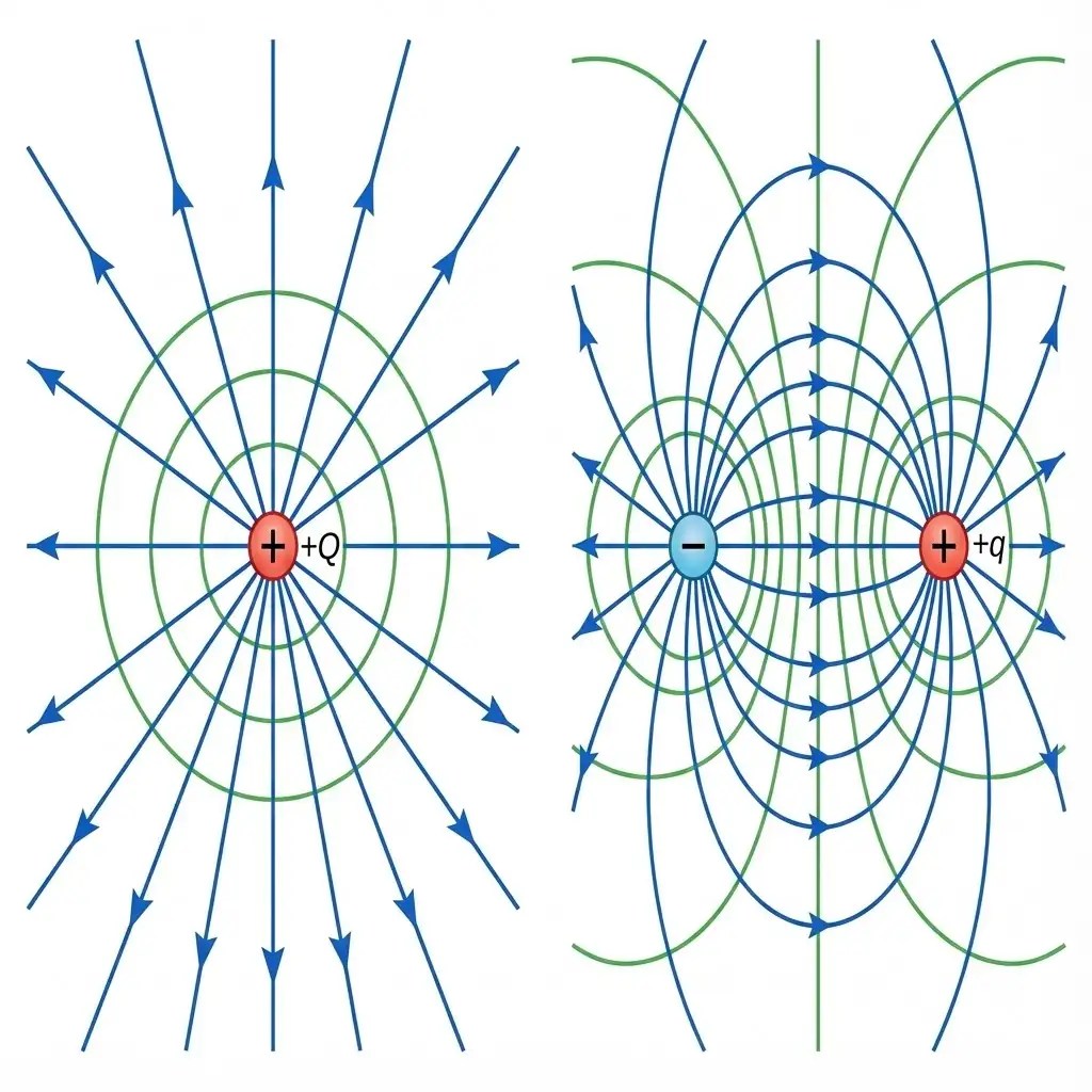
Key Properties
- Work Done: No work is done in moving a test charge over an equipotential surface.
- Field Direction: Electric field is always normal to the equipotential surface at every point.
- Pattern: For a point charge, they are concentric spheres.
3. Potential Energy
Electrostatic potential energy is the work done in assembling a system of charges by bringing them from infinity to their present locations.
Derivation 3: Potential Energy of a System of Charges
3 Marks

Step 1: First Charge
Bring from infinity to . Work done (no external field).
 from infinity to . Work done
  (no external field).
Step 2: Second Charge
Bring from infinity to . Work is done against field of .
 from infinity to . Work is done against field of .

Step 3: Third Charge (Optional)
Bring against fields of and .
 against fields of and .

Final Result
Total :
 :
:

Derivation 4: PE of Dipole in External Field
3 Marks

Step 1: Torque
External field exerts torque on dipole :
 exerts torque on dipole
  :
:

Step 2: Work Done
Work done to rotate dipole from to :
 to
to  :
:

![W = pE [-\cos\theta]_{\theta_0}^{\theta_1} = pE(\cos\theta_0 - \cos\theta_1)](https://i0.wp.com/physicsqanda.com/wp-content/ql-cache/quicklatex.com-b43b7496457a050ba1f8584959029000_l3.png?resize=309%2C25&ssl=1 "Rendered by QuickLaTeX.com")
Final Result
Setting reference (where ):
 (where
  ):
):

4. Electrostatics of Conductors
Important Results
- Inside: Electrostatic field is zero everywhere inside the conductor.
- Surface: Electric field is normal to the surface.
- Potential: Constant throughout volume and surface.
- Shielding: Electric field inside a cavity is zero.
5. Capacitance & Dielectrics
Capacitance is the ratio of charge to potential difference:  .
.
Derivation 5: Parallel Plate Capacitor
3 Marks

Step 1: Electric Field
Using Gauss’s Law, field between plates with charge density :
 :
:

Step 2: Potential Difference
For uniform field and separation :
and separation  :
:

Final Result
Using :
:

Derivation 6: Effect of Dielectric on Capacitance
3 Marks

Step 1: Polarization
Dielectric polarized creates induced surface charge .
Net field (since ).
 .
.
Net field
 (since
  ).
).
Step 2: Potential

Final Result


6. Combinations of Capacitors
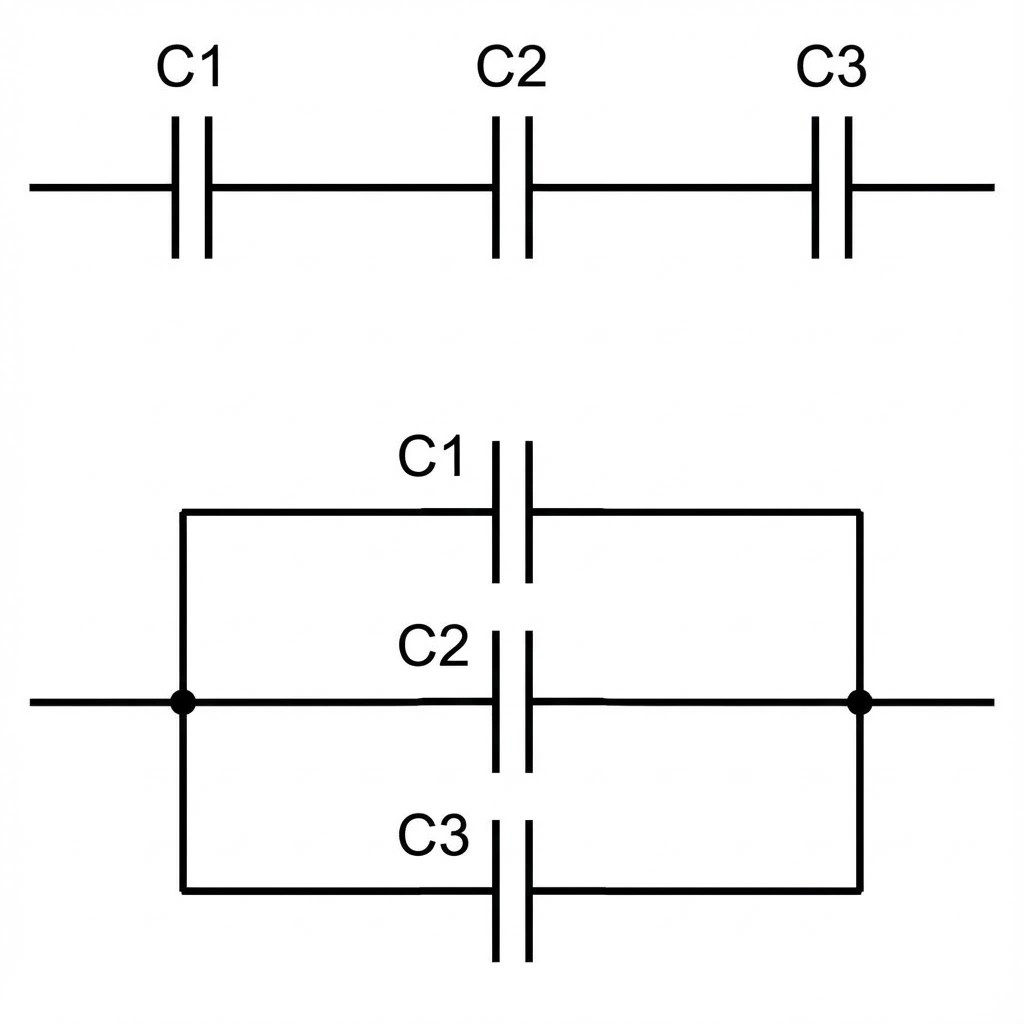
Derivation 7: Capacitors in Series
2 Marks
Logic
In series, Charge (Q) is same on all plates. Potential divides.
divides.

Substitution

Result

Derivation 8: Capacitors in Parallel
2 Marks
Logic
In parallel, Potential (V) is same. Charge adds up.
adds up.

Substitution

Result

7. Energy Stored in Capacitor
Derivation 9: Energy Stored
3 Marks
Step 1: Work Done
Work done to transfer infinitesimal charge against potential :
 against potential
  :
:

Step 2: Integration
Total work to charge from 0 to :
:
![W = \int_{0}^{Q} \frac{q'}{C} dq' = \frac{1}{C} \left[ \frac{(q')^2}{2} \right]_0^Q](https://i0.wp.com/physicsqanda.com/wp-content/ql-cache/quicklatex.com-f4855435f43a4b2c1157f3805399c135_l3.png?resize=208%2C36&ssl=1 "Rendered by QuickLaTeX.com")
Final Result

Energy Density:
Energy per unit volume:

Practice Time!
Ready to test your knowledge? Try 10 solved numericals on Electrostatic Potential & Capacitance: Click here →
Also practice the Question Bank