

 by
by Alternating Current: Question Bank
Practice Set: LCR Series Circuit, Resonance, Power Factor, and Transformers.
Part 1: Multiple Choice Questions (1 Mark)
1. The RMS value of an alternating current  is:
is:
(a) 
(b) 
(c) 
(d) 
The Root Mean Square (RMS) value of a sinusoidal current is peak value divided by
 .
.  .
.
2. In a pure inductive circuit, the current:
(a) Is in phase with voltage
(b) Lags behind voltage by 
(c) Leads voltage by
(d) Lags behind voltage by 
In a pure inductor, the back EMF opposes current change, causing current to lag behind the applied voltage by
 ().
().
3. The power factor of an LCR series circuit at resonance is:
(a) Zero
(b) 0.5
(c) 1
(d) Infinity
At resonance,
 , so the circuit becomes purely resistive (
 ). The phase angle
  , so Power Factor
  .
.
4. A capacitor blocks _________ but allows _________ to pass.
(a) AC, DC
(b) DC, AC
(c) Both, None
(d) None, Both
Capacitive reactance
 . For DC,
  , so
, so  (Blocks DC). For AC, finite reactance allows current.
5. The core of a transformer is laminated to reduce:
(a) Flux leakage
(b) Hysteresis loss
(c) Copper loss
(d) Eddy current loss
Laminations break the path of circulating currents (eddy currents) in the core, reducing heat dissipation.
6. In a series LCR circuit, the voltage across R, L, and C are 40V, 60V, and 30V respectively. The voltage of the supply is:
(a) 130V
(b) 10V
(c) 50V
(d) 70V
 V.
V.
7. The frequency of LC oscillations is given by:
(a) 
(b) 
(c) 
(d) 
The natural frequency of oscillation is
 . Angular frequency is
  .
.
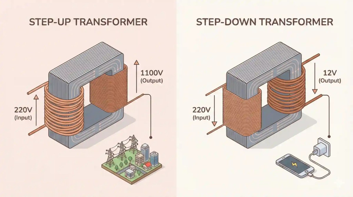
8. In a step-up transformer, the turns ratio is 10:1. If the input voltage is 220V, the output voltage is:
(a) 22V
(b) 220V
(c) 2200V
(d) 110V
 . Here
  . So
. So  V.
V.
9. The average power dissipated in a pure inductor over one complete cycle is:
(a) 
(b) 
(c) Zero
(d) Infinite
Current lags voltage by
. Power factor  . Hence
  .
.
10. An alternating current is given by  . The RMS current is:
(a) 
(b) 
(c)
(d) 
The peak value
 .
.  .
.
Part 2: Assertion-Reason Questions
(B) Both A & R are true, R does NOT explain A.
(C) A is true, R is false.
(D) A is false, R is true.
1. Assertion (A): A capacitor of suitable capacitance is used in an AC circuit in place of a resistor to reduce current.
Reason (R): A capacitor consumes no average power in an AC circuit.
Using a resistor wastes energy as heat. A capacitor offers reactance (
 ) to limit current but consumes zero average power (
 ).
).
2. Assertion (A): When the frequency of the AC source in an LCR series circuit increases, the current in the circuit first increases, reaches a maximum, and then decreases.
Reason (R): Current amplitude is maximum at the resonant frequency  .
.
This describes the resonance curve. Current is max when impedance is min (
) at resonance.
3. Assertion (A): A transformer cannot work on DC supply.
Reason (R): DC supply produces a constant magnetic flux, so no EMF is induced in the secondary coil.
Transformers rely on *changing* magnetic flux (Faraday’s Law) which requires AC.
4. Assertion (A): The voltage across the inductor and capacitor in a series LCR circuit can be greater than the applied voltage.
Reason (R): At resonance, the voltage drops across L and C are equal and opposite, canceling each other out.
Both are true. The voltage amplification occurs due to the Quality Factor (
 ), but the reason given explains why net voltage is low, not why individual voltages are high.
5. Assertion (A): AC meters measure the RMS value of alternating current.
Reason (R): AC meters are based on the heating effect of current, which depends on  .
.
Since heat
 , the average heating corresponds to the mean of squares, hence RMS.
6. Assertion (A): In a series LCR circuit, at resonance, the impedance is equal to the resistance.
Reason (R): At resonance, inductive reactance exceeds capacitive reactance.
Assertion is True. Reason is False; at resonance
, they are equal.
7. Assertion (A): A step-up transformer increases power.
Reason (R): In a step-up transformer, voltage increases, so power ( ) must increase.
False. Energy is conserved. If voltage increases, current decreases proportionally. Power output
 Power input.
8. Assertion (A): The division of markings on an AC ammeter is not equally spaced.
Reason (R): Heat produced is directly proportional to the square of current ().
Since deflection
 , the scale is crowded at the beginning and spread out at the end (non-linear).
9. Assertion (A): At high frequencies, a capacitor acts as a short circuit.
Reason (R): Capacitive reactance is inversely proportional to frequency.
. As  ,
,  (Short circuit).
10. Assertion (A): 220V AC is more dangerous than 220V DC.
Reason (R): The peak value of 220V AC is  V.
V.
The RMS value is 220V, but the voltage oscillates up to
 V and
V and  V, causing a stronger shock.
Part 3: Important Derivations & Theory
1. Derive the expression for the impedance of a series LCR circuit using the Phasor Diagram method. (5 Marks)
 Key Steps:
1. In series, current
 is same. Take as reference phasor.
2.
 is in phase with .
  leads by .
  lags by .
3. Net reactance voltage
 (assuming
  ).
).4. Resultant
 .
.5. Substitute
 :
: ![I^2 Z^2 = I^2 [R^2 + (X_L - X_C)^2]](https://i0.wp.com/physicsqanda.com/wp-content/ql-cache/quicklatex.com-e8d74345600eb8d0f77efc4d1c4e9c0e_l3.png?resize=224%2C20&ssl=1 "Rendered by QuickLaTeX.com") .
.6.
 .
.
2. Define Root Mean Square (RMS) value of AC. Derive the relation between  and . (3 Marks)
Derivation:
1.
 .
.2. Using
 , integral over full cycle gives
  .
.3. Equate to DC heat
 .
.4.
 .
.
3. Draw a labelled diagram of a Step-Up Transformer. Derive the relation between turns ratio, voltage, and current. (3 Marks)
1. Induced EMF per turn is same.  and
and  .
.2. Divide equations:
 .
.3. Assuming ideal transformer (Power In = Power Out):
 .
.4.
 .
.
Part 4: Numericals
1. A series LCR circuit with  ,
,  H and
H and  is connected to a variable-frequency 200V AC supply. When the frequency of the supply equals the natural frequency of the circuit, what is the average power transferred to the circuit in one complete cycle?
 .
.Current
 A.
A.Power
 . Since
  ,
,  .
. W.
W.
2. A  resistor is connected to a 220V, 50Hz AC supply. (a) What is the RMS value of current? (b) What is the net power consumed over a full cycle?
 A.
A.(b)
 W.
W.
3. Obtain the resonant frequency  of a series LCR circuit with
  H,
H,  and
and  . What is the Q-value of this circuit?
 .
. rad/s.
Q-value
 .
.
Part 5: Case Study
Case Study: Tuning a Radio (Resonance)
The phenomenon of resonance is commonly used in the tuning mechanism of a radio or a TV set. The antenna of a radio accepts signals from many broadcasting stations. The signals picked up in the antenna act as a source in the tuning circuit of the radio, so the circuit can be driven at many frequencies. But to hear one particular station, we tune the radio. In tuning, we vary the capacitance of a capacitor in the tuning circuit such that the resonant frequency of the circuit becomes nearly equal to the frequency of the radio signal received.
- What is the condition for resonance in a series LCR circuit?
- At resonance, what is the impedance of the circuit?
- A radio can tune over the frequency range of a portion of MW broadcast band: 800 kHz to 1200 kHz. If its LC circuit has an effective inductance of
 , what must be the range of its variable capacitor?
 - Why is the Q-factor important in tuning?
 , what must be the range of its variable capacitor? or
  .
.2. Impedance is minimum and purely resistive (
 ).
).3. Using
 .
.For 800 kHz:
 pF. For 1200 kHz:
  pF.
pF.Range: 88 pF to 198 pF.
4. Q-factor determines the **sharpness** of resonance. Higher Q means better selectivity (ability to distinguish between close frequencies).


